티스토리 뷰
조도 및 온도 센서, 데이터 로거
Light and Temperature Logger


Introduction
OK now that we have introduced both the RTC and the SD card and verified that they're working, we can move onto logging!
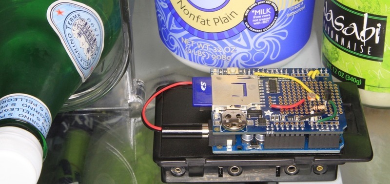
We'll use a pretty good & detailed demonstration to show off the capabilities of this most awesome data logging shield: We'll log both temperature and relative light levels to determine:
- How much does the temperature in a fridge vary as the compressor turns on and off?
- Does keeping the door open cause a big temperature drop? How long does it take for it to cool down?
- Does the light inside really turn off when the door is closed?

Build It!

Items you'll need:
- Arduino (of course!) a Atmega328 type is best - we always recommend going with an official 'classic' Arduino such as the Uno.
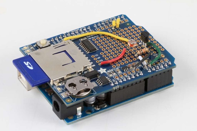
- Adafruit data logger shield - assembled
- SD card formatted for FAT and tested using our example sketch
- CdS photocell and a matching 10K pulldown resistor
- Temperature sensor with analog out, such as TMP36
- Battery pack such as a 6-AA 'brick' and a 2.1mm DC jack.
- or you can use a 9V clip for a power supply but a 9V powered logger will last only a couple hours so we suggest 6xAA's
- Some 22 AWG wire, soldering iron, solder, etc.
You can get most everything in that list in a discounted pack in the Adafruit shop!

The sensors
We'll use two basic sensors to log data, a CdS photocell to track light (this will tell us when the door has been opened) and a semiconductor temperature sensor to log the ambient fridge temperature.
We will wire the sensors as shown in the diagram below.
Note that we connect ARef, the power pin of the temp sensor, and the light sensor to 3.3V not to 5.0V - we do this because the 5V line is very noisy and the 3.3V regulator is better filtered. In the actual board we used the 3.3V line from the datalogger's regulator, see the images below - in theory its the same as the one off of the Arduino but we trust ours more.

Wiring it up
The prototyping area on the board is a simple array of holes with soldering pads. The steps below show how we built this circuit and illustrate some some basic circuit prototyping techniques. For clarity, we will use the same color wire as shown in the circuit diagram above:
|
|
Position the sensorsThe sensors could go anywhere on the prototyping area, but we chose this arrangement to simplify connections between the components later on. |
|
|
Prepare some jumpersMeasure a piece of wire (red) long enough to reach from the 3v breakout hole to 1/2" past the temperature sensor. Strip about 3/4" from one end, and about 1/4" from the other. |
|
|
Install the JumpersPlace the jumpers as shown, with the long stripped ends nearest the sensors. |
|
|
Make the connections
|
|
|
Add more jumpers for the Sensors
And also for the LEDs
|
|
|
Solder and trim all connectionsUsing the same technique of folding the component legs over the jumper - make all connections as shown in the wiring diagram. |

|
|
Prepare the Battery Pack
|
Now your Light Temp Logger is wired and ready for testing!

Use It!

Sensor test
We'll now test the sensors, using this sketch which is a bit of a mashup of the two examples in our tutorials
Copy Code
here
- /* Sensor test sketch
- for more information see http://www.ladyada.net/make/logshield/lighttemp.html
- */
- #define aref_voltage 3.3 // we tie 3.3V to ARef and measure it with a multimeter!
- int photocellPin = 0; // the cell and 10K pulldown are connected to a0
- int photocellReading; // the analog reading from the analog resistor divider
- //TMP36 Pin Variables
- int tempPin = 1; //the analog pin the TMP36's Vout (sense) pin is connected to
- //the resolution is 10 mV / degree centigrade with a
- //500 mV offset to allow for negative temperatures
- int tempReading; // the analog reading from the sensor
- void setup(void) {
- // We'll send debugging information via the Serial monitor
- Serial.begin(9600);
- // If you want to set the aref to something other than 5v
- analogReference(EXTERNAL);
- }
- void loop(void) {
- photocellReading = analogRead(photocellPin);
- Serial.print("Light reading = ");
'HWDesk > ElectronicParts' 카테고리의 다른 글
| Op-Amp를 이용한 삼각파 만들기 (0) | 2020.02.20 |
|---|---|
| Noncontact Voltage Detector 조사 (0) | 2020.02.17 |
| [DataLogger] TRC test (0) | 2020.02.15 |
| Overview of Data-Logger Shield for Arduino (by Adafruit) (0) | 2020.02.15 |
| TMP006 Hookup Guide (0) | 2020.02.13 |
- Total
- Today
- Yesterday
- Innovation&Hurdles
- 오블완
- 혁신과허들
- Innovations&Hurdles
- 전압
- 아두이노
- image
- Innovations
- Video
- 혁신
- 절연형
- 빌리칠드
- DYOV
- 심심풀이치매방지기
- 허들
- 심심풀이
- BSC
- Hurdles
- arduino
- bilient
- 치매
- 배프
- 전류
- ServantClock
- 티스토리챌린지
- BiliChild
- 빌리언트
- 둎
- 치매방지
- Decorator
| 일 | 월 | 화 | 수 | 목 | 금 | 토 |
|---|---|---|---|---|---|---|
| 1 | 2 | 3 | 4 | 5 | 6 | 7 |
| 8 | 9 | 10 | 11 | 12 | 13 | 14 |
| 15 | 16 | 17 | 18 | 19 | 20 | 21 |
| 22 | 23 | 24 | 25 | 26 | 27 | 28 |

